
There exists a lot of confusion and misinformation regarding Earthing of intrinsically safe circuits giving the misconception that Earthing is difficult to achieve. In practice with a clear understanding of what the earthing seeks to achieve the solution is usually relatively straightforward. When the term intrinsic safety earth is used it usually relates to Zener barriers, whereas isolation interfaces earthing is more in line with standard process/instrument earths.
Zener Barrier earth
 The Zener barrier, standing alone, controls with certainty the maximum values of voltage and current available between its output terminals which will be connected to the hazardous area circuit. However, without a further connection, it cannot control the potential which may occur between either of its output terminals and local earth in the hazardous area.
As accidental earth faults in the hazardous area are considered liable to occur, then this further earth connection is an essential ingredient in ensuring that the system is in fact intrinsically safe.
EN 60079-14 clause 16.2.3 tell us that the Zener barrier earth terminals should be:
- 'connected to the equipotential bonding system by the shortest practicable route, or ..'
- 'for TN-S systems only, connected to a high-integrity earth point in such a way as to ensure that the impedance from the point of connection to the main power system earth point is less than 1Ω. This may be achieved by connection to a switch-room earth bar or by the use of separate earth rods.'
Note the above applies to TN-S systems only (separate neutral and earth conductors in the hazardous area), i.e. not TN-C systems in which both earthing and neutral power return share the same conductor, nor IT systems in which the supply neutral is not directly earthed.
For those systems the barrier earth terminals should be connected to the equipotential bonding system by the shortest practical route and is not limited to the 1Ω criteria. This means that in almost all cases a suitable earthing point can be found without any difficulty.
 If a single earth cable is used, then it then the conductor must have a minimum of 4mm² copper.
If 2 separate cables are used, then each must be rated for the maximum possible current which can continuously flow and each to have a minimum of 1.5mm² copper.
In general, it is a better solution to have 2 separate cables each with an earth point of less than 1Ω as it enables one to be disconnected to test the earth connection without affecting the integrity of the intrinsically safe circuit.
This is the traditional representation of barrier earthing.
The connection of the barrier earth conductor to the same earth point as is used for the electricity supply transformer neutral is usually impractical, efforts to physically reach this point often do not make an ideal barrier earth connection.
 In some countries, particularly Germany, it is normal practice to provide an equipotential plane in the form of an electrically conducting mesh underneath the whole site before the plant is erected.
This mesh forms the equipotential bonding system, a connection down to which will provide ideal conditions for furnishing the necessary earth connection to Zener barriers.
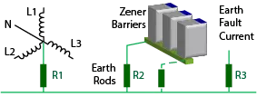 Separate earth rods are permitted, but there remains the need to maintain less than one ohm (R1 + R2) to the main power system earth which can be difficult to ensure. It can be possible for earth fault currents in the power system to cause unwanted voltages to appear at the barrier earth.
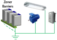 Even if such special provision is not made, then the common grounding of the metal enclosures of plant equipment, motors, luminaires, switchgear and structural components of the building will together usually constitute an equipotential bonding system suitable for the connection of Zener safety barriers.
In the final analysis, both systems, whether or not directly related to the electrical main power system earth point, may in fact be indistinguishable and illustrate that a suitable earth connection point for Zener barriers is usually easy to find.
Cable installations
Where earthed screens are used the preference is to connect the screen to the Earth at the barrier and isolate form any Earth in the hazardous area. To avoid earth loops when field earth isolation is not possible i.e. there exists an unavoidable earth connection in the field then the screen should be isolated from the earth at the barrier end.
These cable screens must be kept isolated from earth in the hazardous area to avoid spurious earth currents being fed back into the barrier earthing system.
Where the field cables are armoured, or are of the mineral-insulated metal-sheathed type, then their armour or sheath is assumed to have contact with earth in the hazardous area, either by their fixings or brass glands, or by deliberate connection.
In these cases, the armour or sheath must not be connected to barrier earth.
Special cases
There are occasions where the installing engineer might reasonably conceive of an alternative earthing arrangement which will provide for a safe situation, particularly where the hazardous area is confined to only a very small part of the plant.
E.g. Such a situation might involve a paint spray booth within a site which is otherwise non-hazardous.
Intrinsically safe instrumentation or control circuits within the booth would be protected by barriers mounted in the control panel immediately outside.
In such a situation, if the metal structure of the booth and the items of plant and equipment within the booth are all adequately earth bonded together then this earth bonding could be extended to include the barrier earth connection and so provide a safe situation in which the intrinsically safe circuits are closely related to the local earth potential within the paint spraying confines.
Isolation Interface Earth
Most engineers when asked about the advantages of isolation interfaces over Zener barriers will say "no intrinsic safety earth is required".
 This is correct for the purposes of the intrinsic safety however the Earth must still be considered.
As well as considering the handling of earth screens for instrumentation, as the cables are floating by definition, attention shall be paid to the danger of electrostatic charging.
If electrostatic charge is a possible issue with floating cables then a route for static discharge must be made.
EN 60079‑14 states: "A connection to earth across a resistance greater than 0,2 MΩ1 for
example for the dissipation of electrostatic charges, is not deemed to be earthing" Therefore a simple solution is to add static discharge resistor (typically 1MΩ) to one or all cores as appropriate.
Notes
-
The total static discharge resistance is calculated by the parallel combination of discharge resistors.
E.g. for 2 resistors, each 1 MΩ the total resistance is 500KΩ which is unlikely to affect loop currents in instrumentation circuits. ↩